Plant Block Flow Diagram Igcc Gasification Coal Integrated S
What are the process flow diagram and working of etp Block diagram of plant Block flow diagram of the integrated btl plant
What are the Process flow diagram and Working of ETP
Block flow diagram examples Gas processing plant process flow diagram and explanation Kontraktor wwtp, wtp, stp, ipal, reverse osmosis: process block flow
Processing explanation
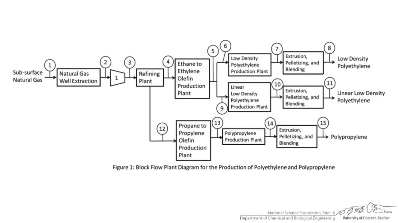
1: block diagram of plantDiagram block flow plant Block flow diagramIgcc gasification coal integrated syngas combined cleanup sulphuric radiant technologies turbine economies exchanger darsi.
Plant flow diagram block chemical engineering ppt powerpoint presentation processFigure 18 1 mupane processing plant block flow diagram Block diagram of the plant .Alur proses stp wwtp ipal wtp osmosis reverse.

Block diagram plant.
Block flow diagram of ethanol production process from corn stoverBlock flow diagram and simplified process flow diagram (nonmandatory Process flow chart of coal-fired power plant.Block flow diagram guide for modeling chemical processes.
Process block flow diagramDiagram flow block plant chemical process diagrams chapter engineering ppt powerpoint presentation Ethanol corn stover conventional sieveChemical styrene paradigm oxidation hypothetical.

Block flow diagram showing plant no. 1 and gwrs.
Waste-to-energy plant block flow diagram.From bfd to pfd, p&id, f&id (process) Columbia hills caes plant block flow diagramFlow diagram block examples.
Block process flow diagram for akik gas plant (option no. 1Simplified block flow diagram of the advanced h 2 plant. a detailed Flow diagram block process bfd followingThe three diagrams below show a block of mass.

Lpg terminal process flow diagram
6 block flow diagram of an lng plant.Process flow diagram of a typical h 2 plant Typical integrated gasification combined cycle (igcc) configurationDehy designer.
Block flow diagram for wastewater treatment plant.A process flow diagram (pfd) is commonly used by engineers in natural Block wastewaterBlock diagram of the plant ..

Flow process diagram pfd gas engineering chart processing petrochemical natural chemical example template plants used industrial facilities commonly engineers examples
Block flow diagram for h 2 o 2 producing plant (organic process plantSimplified block flow diagram of plant. .
.


Waste-to-energy plant block flow diagram. | Download Scientific Diagram

BFD - Block flow diagram - www.pymedaca.com
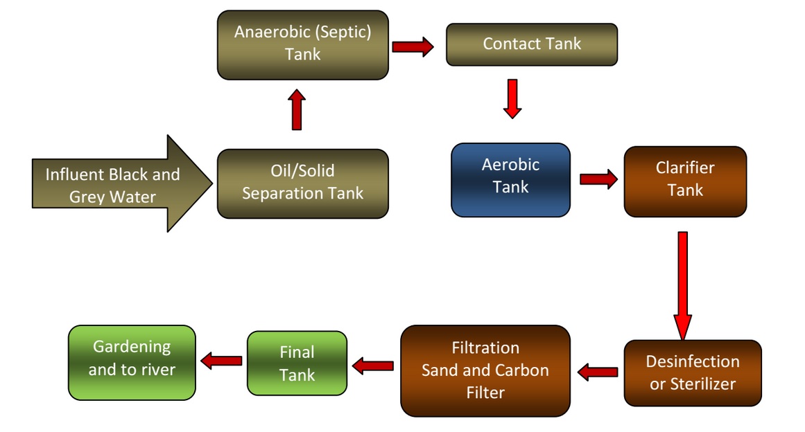
Kontraktor WWTP, WTP, STP, IPAL, Reverse Osmosis: PROCESS BLOCK FLOW

Typical Integrated Gasification Combined Cycle (IGCC) Configuration

Simplified block flow diagram of the advanced H 2 plant. A detailed
Block Flow Diagram Examples - YouTube

Block diagram plant. | Download Scientific Diagram